Formula Student
Work as Chassis Lead
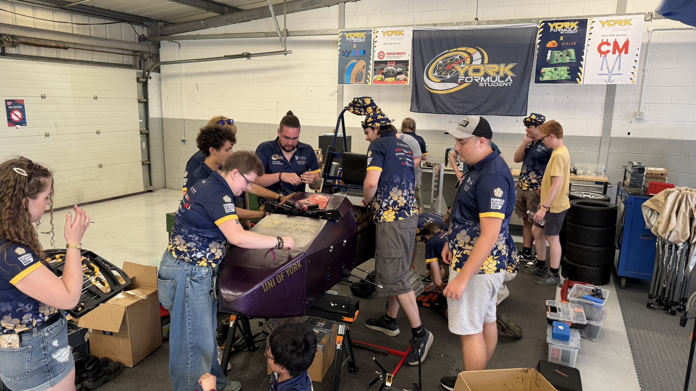
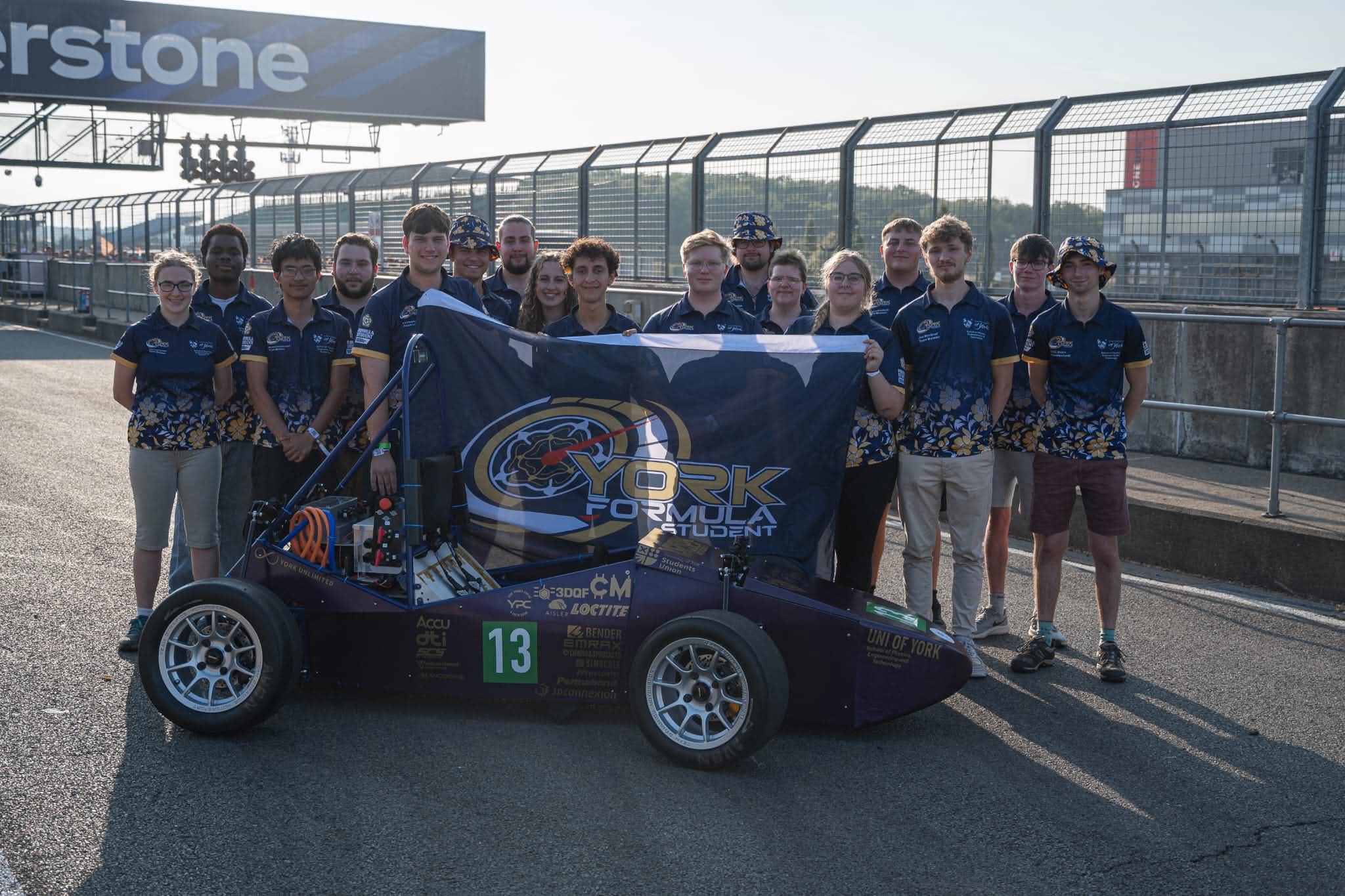
Lead the development of the 2026 York Formula Student car, YFS03, which is the team's first fully integrated car.
01
Chassis Design
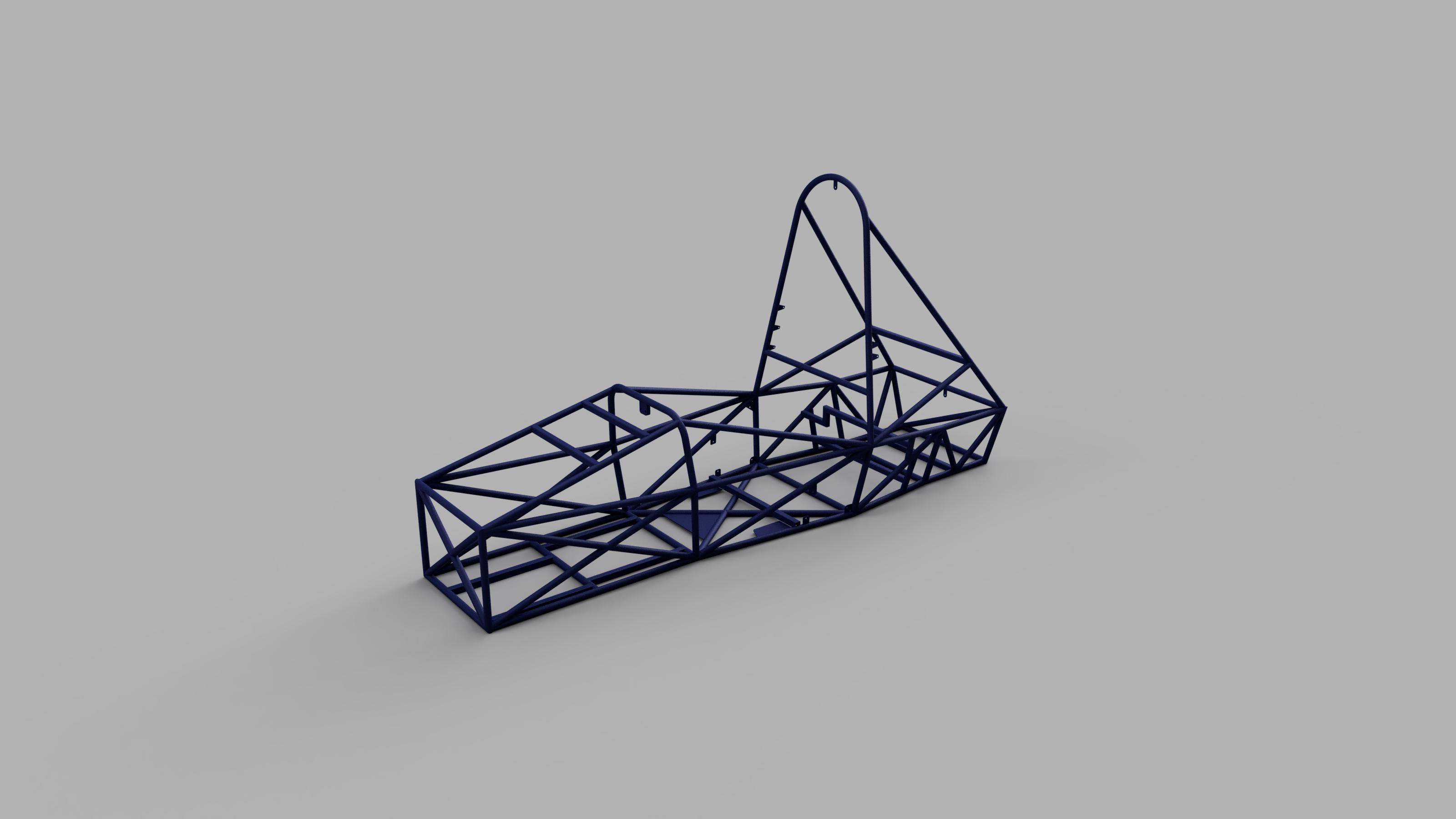
The year started with the design of the chassis, with weight reduced by 5 kg, length shortened by 200 mm and width reduced by 50 mm. I designed the frame in Autodesk Inventor using the frame tool, allowing each tube, notch and joint angle to be modelled accurately. I then validated the design using FEA, applying representative calculated load cases and checking that predicted stresses remained below the material yield strength while also assessing chassis deflection and stiffness. I worked closely with the dynamics lead to ensure that suspension pickup points and shock mounting was optimal.
02
Chassis Tube Preparation
To begin the manufacturing process, I was trained to use a cold-cut metal saw, allowing me to begin processing the cutting list generated from the Inventor model. I optimised the cutting sequence for each stock length to minimise material waste, leaving additional material for notching. Several tubes were also accurately mitred on the saw using a bevel box and digital angle gauge.
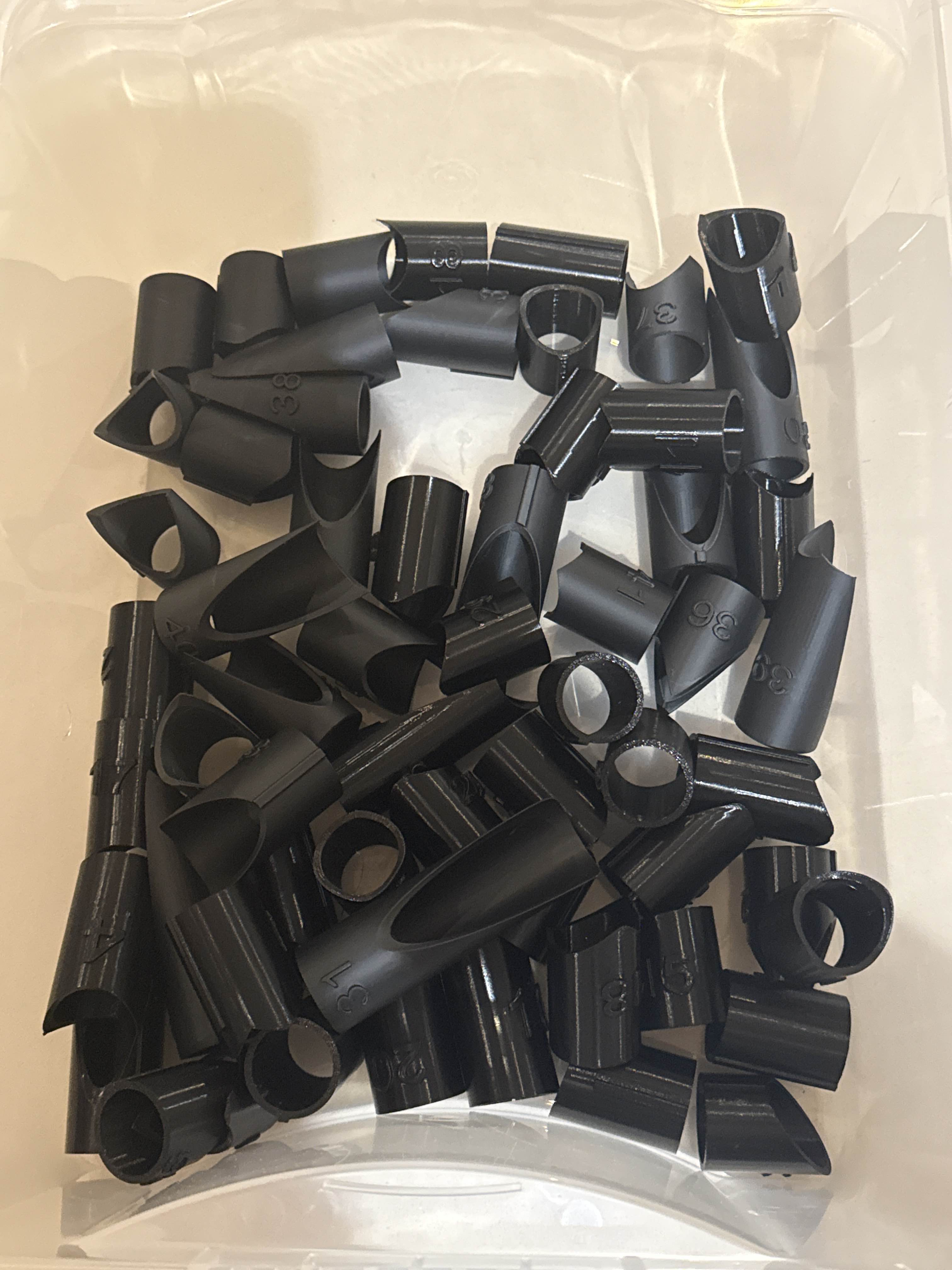
To improve the accuracy and repeatability of the notching process, I developed a system of 3D-printed notching templates derived directly from the CAD geometry of each tube. These templates allowed the position, profile and angle of each notch to be accurately transferred onto the tube before material was removed using the belt tube notching machine.
In total, I produced approximately 40 notches during the manufacture of the chassis. Following welding, the completed frame achieved dimensional accuracy within approximately 1 mm across its 2 m overall length, demonstrating the effectiveness of the CAD-driven manufacturing process and careful tube preparation.
03
Chassis Welding
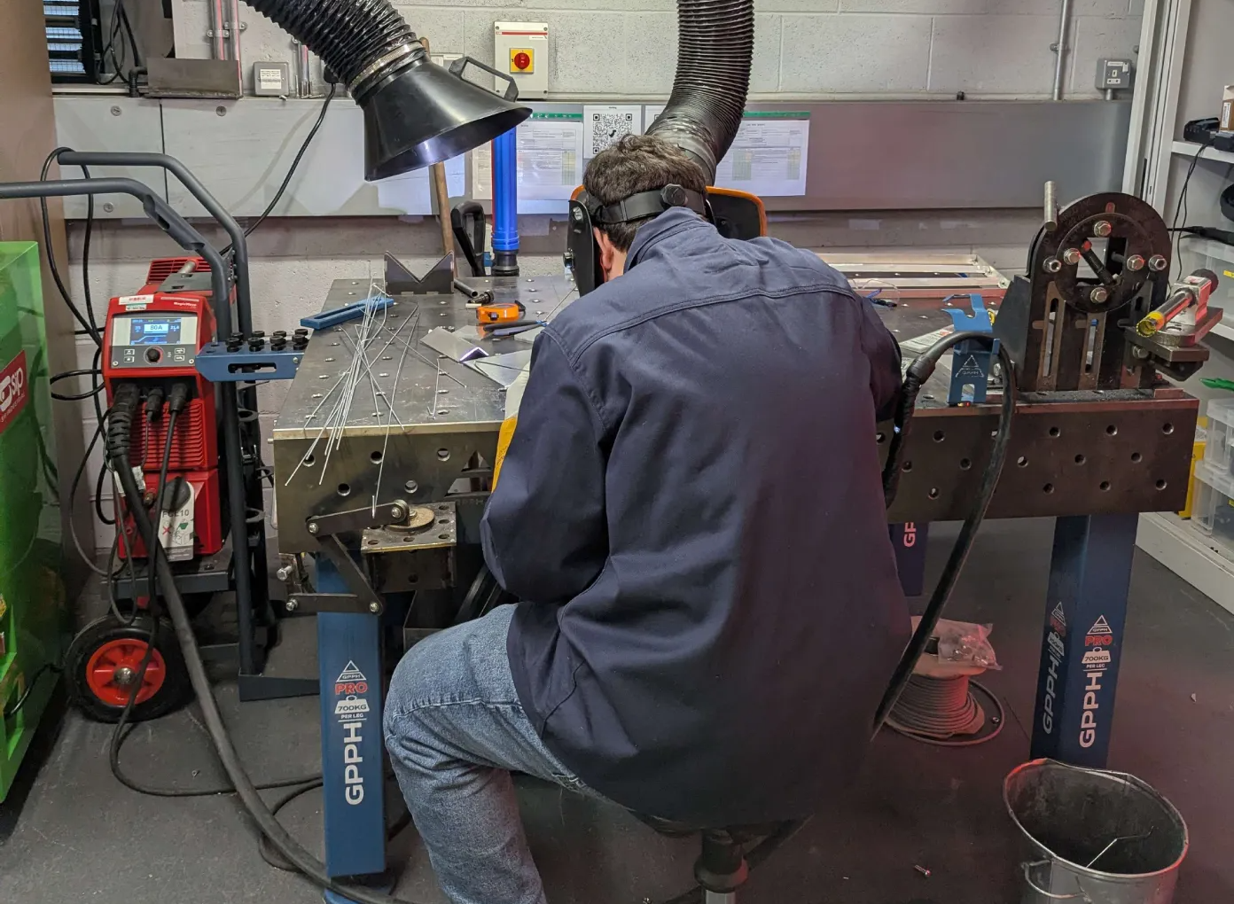
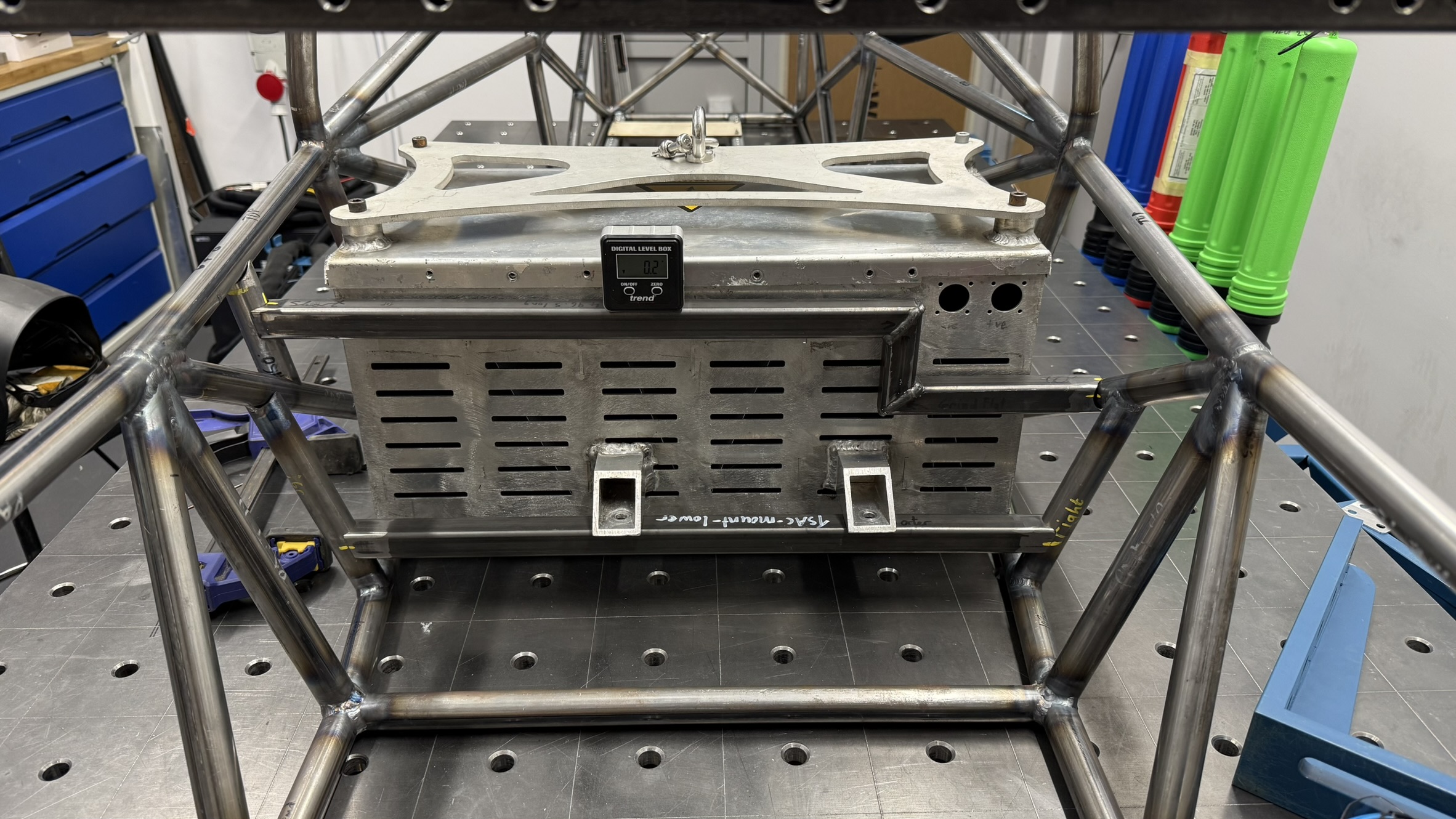
The chassis was TIG welded by myself, the Dynamics Lead and a university technician. Throughout the welding process, dimensions were regularly checked using 1 m vernier callipers to maintain alignment. Despite manufacturing the chassis without dedicated jigs or fixtures, the completed frame achieved a maximum deviation of approximately 1 mm from the CAD model across the length of the vehicle.
Alongside manufacturing, we developed a detailed CAD model of the complete vehicle, incorporating components down to individual fasteners. This allowed mounting brackets and tabs to be designed and positioned accurately before fabrication. Tabs were all cut using a fibre laser. Key features, including suspension mounting points and accumulator mounting structures, could therefore be located directly from the CAD model, improving dimensional accuracy and ensuring correct integration of the vehicle's mechanical systems.
04
Suspension
I worked alongside the Dynamics Lead and chassis team to develop the vehicle's suspension system. My main responsibility was ensuring the suspension components met the required strength, reliability and safety requirements through FEA, while also considering manufacturability.
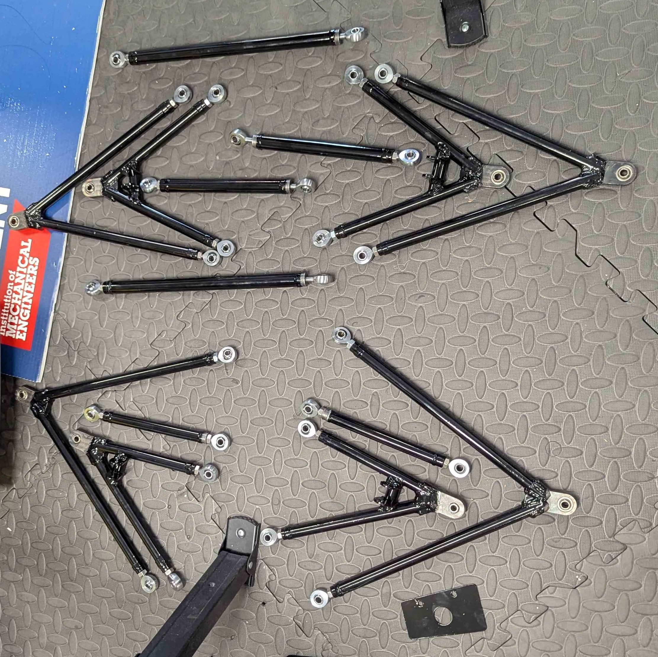
The wishbones were manufactured from 15.8 mm steel tubing. I designed machined steel bearing housings to provide a press fit for spherical bearings before being welded to the suspension tubes. At the chassis end, I designed M8 weld-in threaded bungs to accept high-strength rod ends, providing adjustment and connecting the wishbones to custom-machined chassis mounts.
The upper wishbones also incorporated mounting points for the pushrod suspension system. A pushrod system was selected as it has more optimal load paths into the chassis, reducing bending loads on any members.
05
Wheel Uprights
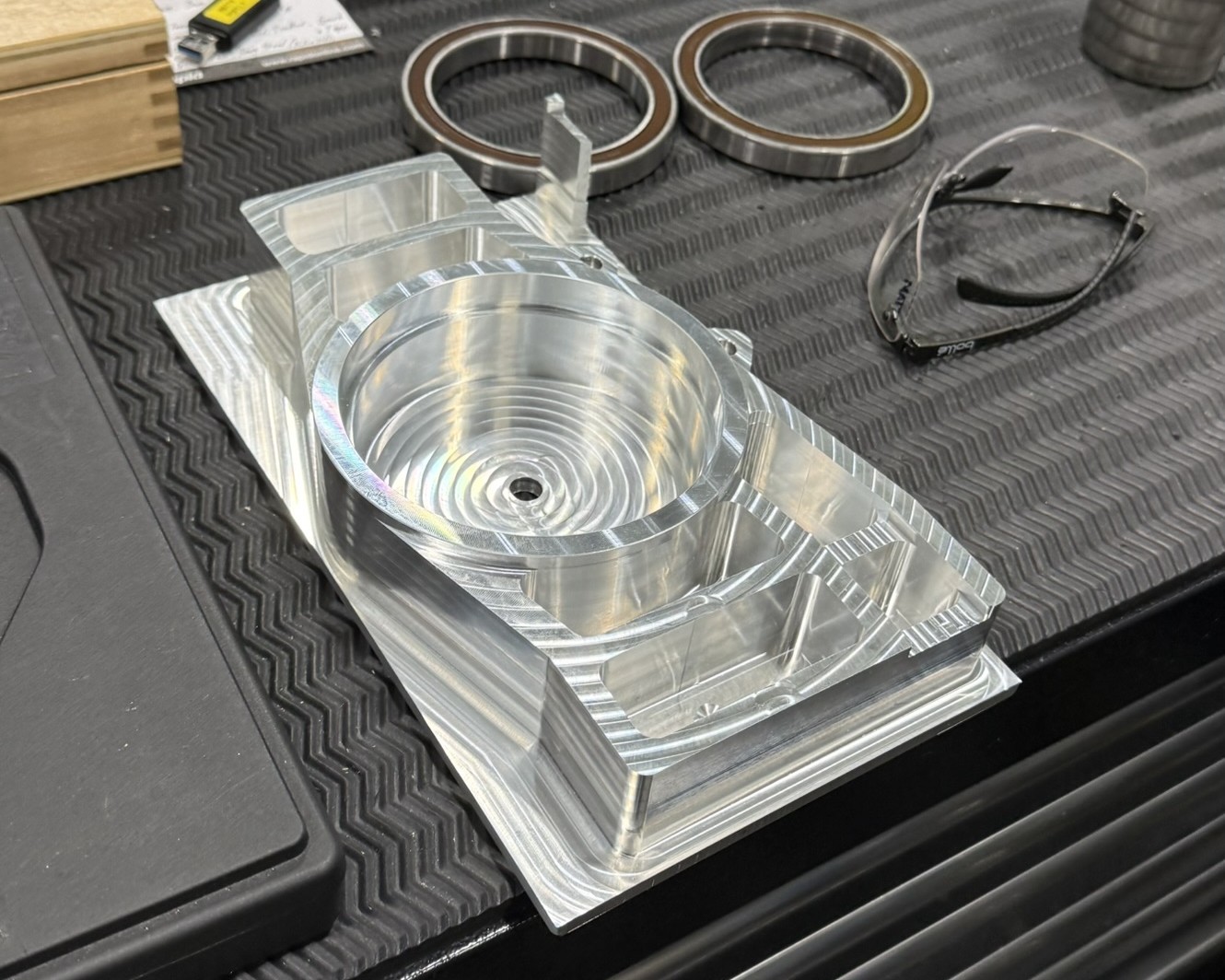
I designed the aluminium uprights for the rear wheels. The purpose of these components is to connect the wheel hubs, and therefore the wheels, to the vehicle's suspension.
A significant part of the development involved FEA validation to ensure that shock loads from the wheel hitting a kerb or bump could be safely transferred through the upright without causing excessive stress or deformation.
The uprights feature upper and lower suspension mounting points, along with a tie-rod mount used to control the toe of the wheel. I worked with the machinist to ensure the parts were suitable for manufacturing, including calculating the required bearing tolerances. I also avoided tapered geometry and incorporated appropriate radii and chamfers to simplify machining.
06
Powertrain
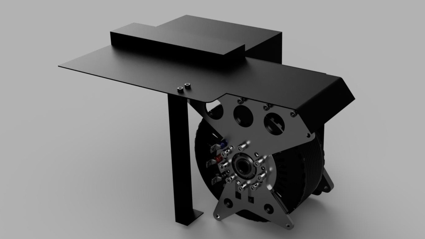
My contribution to the powertrain focused on the motor mounting system, chain drive and scatter guard, with consideration given to packaging, structural loading and drivetrain safety.
To improve packaging efficiency, I utilised the existing accumulator mounting bars as structural mounting points for the motor. I designed a new 6 mm stainless steel motor mount, based on the original DTI mounting geometry but with revised mounting points to interface with the chassis bars. The mount was then laser cut and bolted to the motor.
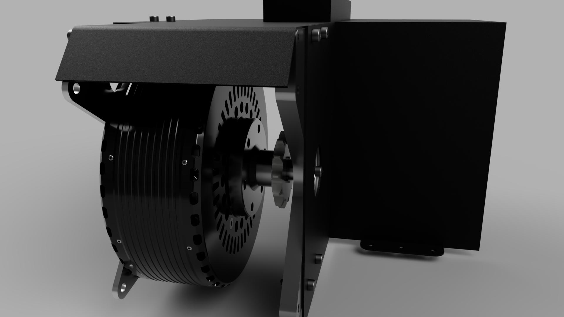
Due to the high motor torque and chain tension, the primary mount would be subjected to significant torsional force. To provide additional support, I designed a second mounting point on the opposite side of the drivetrain. Power is transferred from the motor through a custom splined flange adapter, which interfaces with the motor output and provides the required spline for the front sprocket. The adapter also incorporates a 20 mm support shaft running in a bearing.
I designed a secondary motor mount from 15 mm aluminium to house this bearing using a press-fit interface. Supporting the drivetrain shaft on the opposite side of the chain helps resist the twisting moment generated by chain tension.
For drivetrain safety, I also designed a custom 2 mm steel scatter guard enclosing the chain, sprockets and rotating inboard spool. The components were laser cut before being TIG welded and assembled by me for installation within the chassis.
07
Electronics Integration
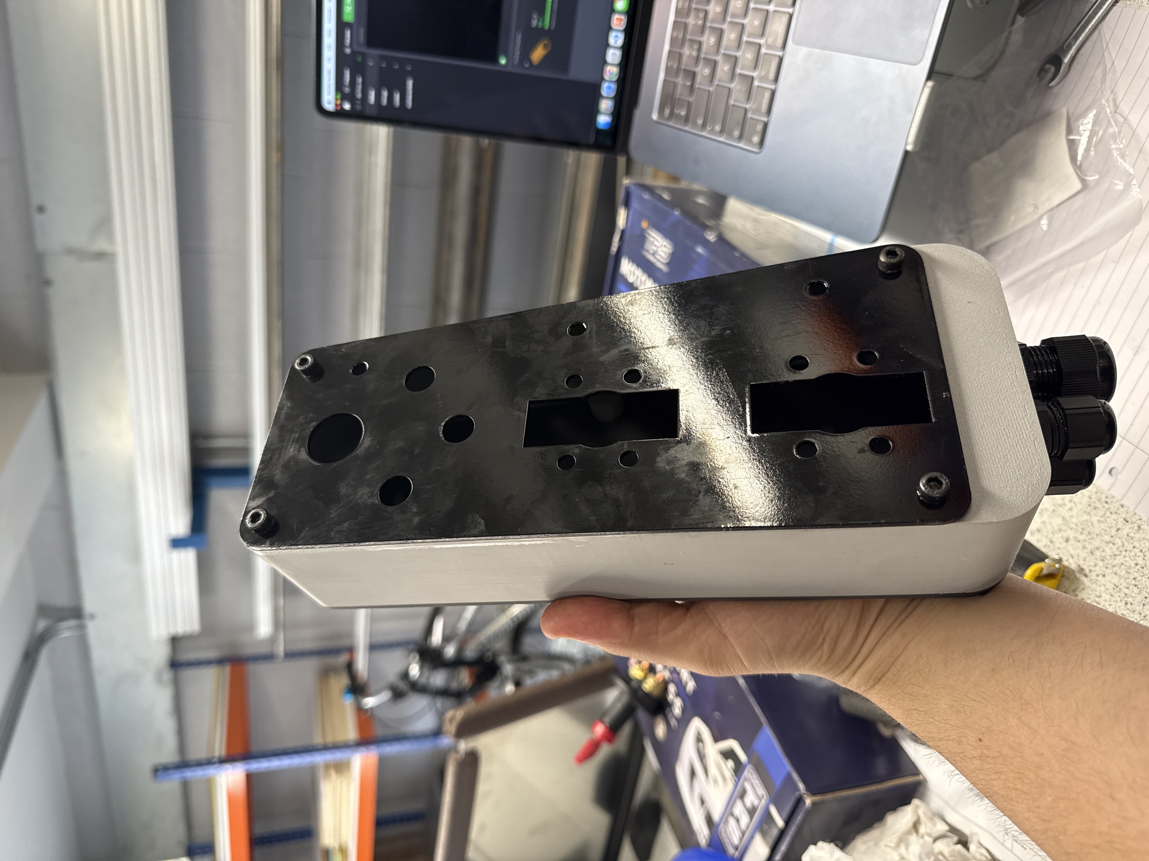
I contributed to the integration of both the high-voltage and low-voltage electrical systems across the vehicle. For the HV system, I designed and assembled the HV distribution box, which houses the energy meter, current sensor and emergency disconnect, while also providing dedicated test points for safely measuring the inverter capacitor voltage during shutdown procedures.
The enclosure was designed from interlocking laser-cut aluminium panels, which I TIG welded into the final assembly. I completed the internal HV wiring and component integration, using appropriately rated UL94-V0 materials and ensuring all exposed conductive enclosure components were correctly bonded to chassis ground.
For the low-voltage system, I supported the manufacture of the vehicle wiring harnesses, including connector selection, crimping and integration of components such as the brake light, brake switch and dashboard status indicators. I also designed and manufactured a sealed side control panel containing the LV master switches and diagnostic test points, with consideration given to environmental protection for wet conditions.
08
Result
As Chassis Lead, my work contributed to delivering York Formula Student's first fully running vehicle and a significant improvement in the team's competition performance. At FSUK, the team increased its score from 96.8 to 170.4 points and improved from 52nd of 59 teams to 45th of 64. Alongside leading the chassis development, I worked across suspension, powertrain, high and low-voltage integration and final vehicle assembly, helping turn the car from a CAD design into a complete and operational vehicle. The role gave me experience not only in detailed engineering design and manufacture, but also in coordinating multidisciplinary work and solving integration problems under the time constraints of delivering a competition vehicle.